Introduction
-
-
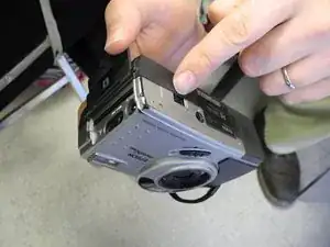
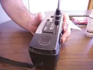
Locate the silver power button. Gently slide the button to the middle section labeled "off" to shut down camera.
-
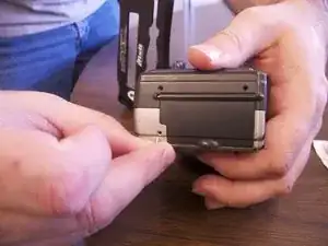
Remove the batteries from the battery compartment located on the underside of the camera.
-
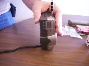
Remove the SD card from the compartment located on the flat, left side of the camera.
-
-
-
Remove the three screws on the flat side of the camera.
-
All of the silver screws go into the side of the camera that is silver.
-
All of the black screws go into the side of the camera that is black.
-
-
-
Remove the four screws from the bottom of the camera.
-
All of the silver screws go into the side of the camera that is silver.
-
All of the black screws go into the side of the camera that is black.
-
-
-
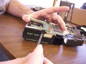
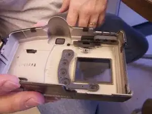
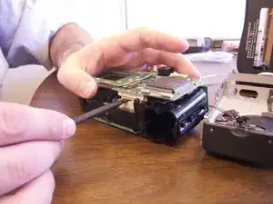
Separate the front and the back pieces of the cameras plastic casing using a spudgerm here.
-
WARNING: When pulling the front plastic casing, be careful of the wires that are connected to the aperture control.
-
Use minimal force so that the plastic casing does not break.
-
When separating the small silver sliding, indicator for view/off/playback may fall out.
-
The plastic viewing window located on the top of the camera may also become lose and fall out.
-
-
-
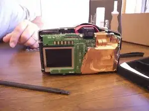
Remove copper sheet from the front paneling and back.
-
You will need to use a spudger to unsolder the copper paneling
-
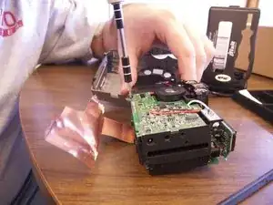
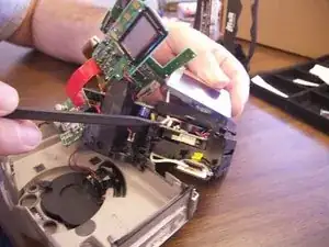
Use the spudger to separate the back circuit board from the camera
-
-
-
The picture viewing screen is glued to the backing as well as wired in with pink and white wires.
-
Exert minimal force required to pull the screen loose from the camera
-
Remove the pink and white wiring from the internal paneling. These wires are soldered in
-
Remove the orange data hookup cable which feeds into the back circuit board
-
-
-
Once all wires have been detached and the old screen has been removed place the new screen into the camera.
-
Insert data hookup into the back of the camera and into the new screen
-
Re-solder the new pink and white wire onto the internal circuit board
-


To reassemble your device, follow these instructions in reverse order.